Advanced Welding of 347H Stainless Steel Pipes: Techniques and Best Practices
The welding of 347H stainless steel pipes requires a careful balance between austenitic structure control and niobium stabilization. Proper welding ensures high-temperature strength while preventing intergranular corrosion, hot cracking, and microstructural degradation. As a leading stainless steel pipe manufacturer, Ganyeah Group provides technical expertise and reliable 347H stainless steel welding solutions for demanding power, chemical, and solar energy projects.
1. Welding Material Selection
Filler Metals
- Standard Filler Wire:
Use ER347 (AWS A5.9 ER347) containing niobium (Nb ≥ 8 × C%) to form stable niobium carbides (NbC), preventing chromium carbide precipitation and intergranular corrosion. - Self-Shielded Wire:
TGF-347 flux-cored wire includes deoxidizers such as aluminum and titanium, forming a protective slag during welding. It eliminates the need for argon purging and is ideal for all-position pipe welding (6G position), improving efficiency by over 30%. - Welding Electrode:
Manual welding may use E347 (AWS A5.4 E347-16). Dry the electrodes at 150–200°C for one hour before use to ensure moisture removal.
Avoided Filler Metals
Do not use titanium-stabilized fillers (e.g., ER321) — titanium burns off easily above 600°C, reducing stabilization and increasing intergranular corrosion risk.
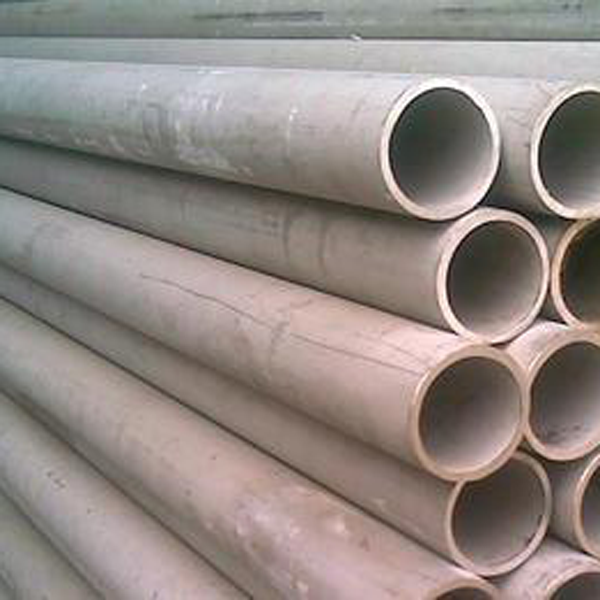
347H stainless steel pipes by Ganyeah Group
2. Welding Methods and Applications
| Welding Method | Application Range | Process Features |
|---|---|---|
| TIG (GTAW) | Thin-walled pipes (≤6 mm), all-position welding | Argon shielding (99.99% purity), current 80–150A, voltage 12–18V, low heat input (≤1.0 kJ/mm), ideal for precision parts. |
| MIG (GMAW) | Medium-wall pipes (6–20 mm) | Shielding gas 98% Ar + 2% O₂, current 200–300A, voltage 22–28V, high deposition efficiency, interpass temperature ≤150°C. |
| Plasma Arc Welding (PAW) | Ultra-thin pipes (≤1 mm), high-precision joints | Concentrated energy, narrow heat-affected zone, rear argon protection (5–10 L/min), suitable for aerospace. |
| Submerged Arc Welding (SAW) | Thick-wall pipes (≥20 mm), straight sections | Use HOCr19Ni11Nb wire with basic flux (e.g., SJ601), current 500–800A, voltage 28–34V, remove slag after welding. |
3. Pre-Weld Preparation
- Beveling:
Machine or plasma-cut bevels (remove oxidation afterward). Recommended V-type (60±5°) or U-type (radius 3–5 mm) groove with 1–2 mm land and 2–3 mm root gap. - Surface Cleaning:
Clean with acetone or alcohol within 20 mm of the joint area. Use stainless steel brushes only to avoid iron contamination. - Backside Protection:
For non-self-shielded processes, fill the inner pipe with high-purity argon (15–20 L/min) until oxygen <50 ppm to prevent chromium-depleted layers.
4. Welding Process Control
- Heat Input:
Keep heat input ≤1.5 kJ/mm (≤1.0 kJ/mm for thin pipes). Use low-current, high-speed welding with narrow beads to minimize NbC precipitation and grain growth. - Interpass Temperature:
Maintain between 100–150°C using infrared monitoring to prevent over-aging of the weld metal. - Technique:
Maintain a 2–3 mm arc gap for TIG; for MIG, keep 15–20 mm wire stick-out. For fixed pipes, use upward or horizontal progression to control the molten pool and prevent sagging.
5. Post-Weld Treatment
Weld Cleaning:
Remove slag and spatter using stainless tools; never use carbon steel brushes.
Heat Treatment:
- Solution Annealing: For thick-wall pipes (>15 mm), heat to 1020–1100°C and water quench to dissolve NbC and restore corrosion resistance.
- Stress Relief: For cyclic service components, perform annealing at 650–700°C (1–2 hours per 25 mm wall), then cool below 300°C in air.
Surface Finishing:
Pickling and passivation (20% HNO₃ + 5% HF for 30 minutes) or mechanical polishing (Ra ≤1.6 μm) enhance surface corrosion resistance.
6. Quality Inspection and Defect Prevention
Non-Destructive Testing:
- Radiographic Testing (RT):
In accordance with ASTM E155 or GB/T 3323, Grade I standard; no lack of fusion or porosity >1.5 mm allowed. - Penetrant Testing (PT):
Fluorescent solvent-based penetrants, sensitivity Level B for fine surface crack detection.
Common Defects and Countermeasures:
- Hot Cracking: Caused by NbC segregation — control S ≤0.030%, P ≤0.035%, and minimize restraint stress.
- Intergranular Corrosion: Ensure Nb/C ≥8, avoid excessive heat input, and apply post-weld solution treatment.
- Porosity: Use high-purity argon (dew point ≤−40°C) and ensure thorough joint cleaning.
7. Engineering Case Studies
Power Plant Boiler Tubing
In a 600°C supercritical unit, Φ108×12 mm 347H stainless steel pipes were welded using TIG root (ER347, φ2.4 mm, 120A) and SMAW fill passes (E347, φ3.2 mm, 100A). Post-weld 100% RT achieved a 98% first-pass qualification rate.
Molten Salt Solar Tank Welding
For a 50 MW solar project in Qinghai, TGF-347 self-shielded wire (φ1.2 mm) was used for full-position welding without argon purging. Welding speed reached 0.8 m/min, and magnetic particle testing (MT) confirmed crack-free welds, achieving over 10 km of defect-free joints.
The welding process of 347H stainless steel pipes focuses on matching niobium-stabilized fillers, precise heat input control, and targeted post-weld treatments. When applied correctly, these methods balance high-temperature strength and corrosion resistance, ensuring weld integrity equivalent to base metal performance.
With extensive experience in high-temperature alloy fabrication, Ganyeah Group provides advanced stainless steel pipe welding solutions that meet the demanding requirements of power, chemical, and renewable energy sectors worldwide.